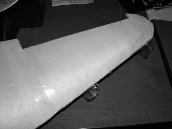
Three foam sheets contain all of the parts required to build the WattsWing Mig-3 wing. There will be two of the sheet containing the wing tip panels and the ribs. The third sheet contains the wing root panels.
Equipment required to complete the wing includes:
1.) Gorilla glue – polyurethane glue
2.) Epoxy
3.) Water – preferably in a squirt bottle.
4.) Sharp Exacto knife
5.) Straight pins
6.) Flat working surface
7.) Ruler or straight edge
8.) Packing tape
9.) Clamp
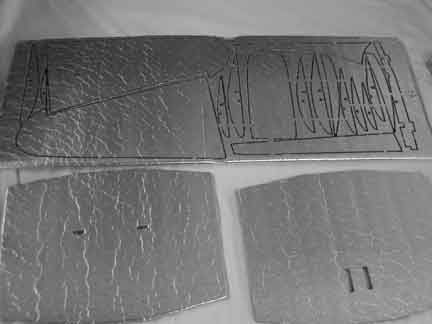
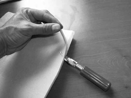
Cut out all of the Wing parts and remove the protective paper from both sides. Use one hand to hold the part to the table and the other to peel the paper off at a very shallow angle.
Identify the Parts
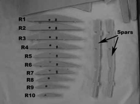
There are 10 sizes of ribs, order them largest to smallest and use a pencil to label them Note the placement of the hole for the carbon fiber spar shaft—it can be used to identify the ribs in the wing root. The foam spars are used to locate the ribs correctly.
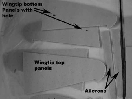
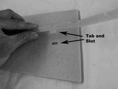
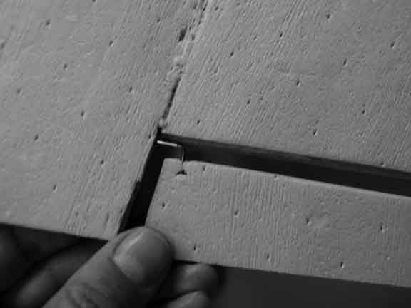
The wing tip panels are identified as shown in the photo. The bottom wing tip panels have a horizontal slot in them for the wing spar. Be sure to build both a right and a left wing tip.
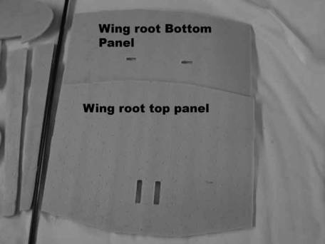
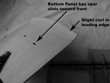
The wing root bottom panel has two horizontal slots cut into it and the slots are oriented toward the leading edge of the wing. The top wing root panel has two slots for the aileron control linkage, which are oriented toward the trailing edge of the wing.
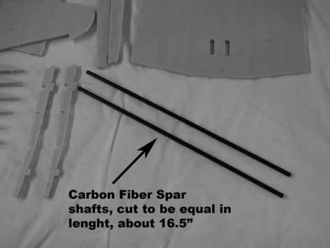
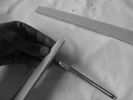
Cut the long carbon fiber shaft in half, resulting in the two wing carbon fiber spar shafts.
Assemble the outer
wing sections
To begin assembly of the wing, snap the foam wing spar into the slot in the wing tip bottom panel.
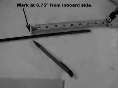
Place a mark on the wing spar shaft 6.75 inches from the wing root end of the shaft. This will mark the location of the dihedral break in the wing-the point where the wing tip meets the wing root.
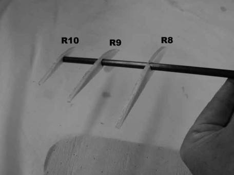
Slide R10, R9 and R8 onto the wing spar shaft. Oreint them roughly as shown toward the wing tip end of the shaft.
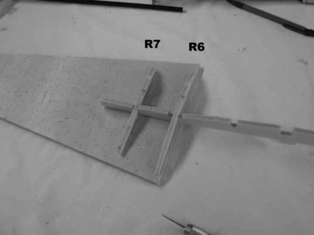
Snap rib R7 and R6 into the foam spar as shown above. Make them parallel to the inboard edge of the wing bottom panel.
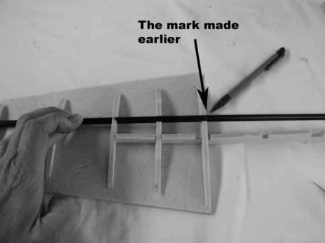
Snap the wing spar shaft into the notches in the top of ribs R7 and R8. Position the mark made on the spar shaft at the outside edge of R6.
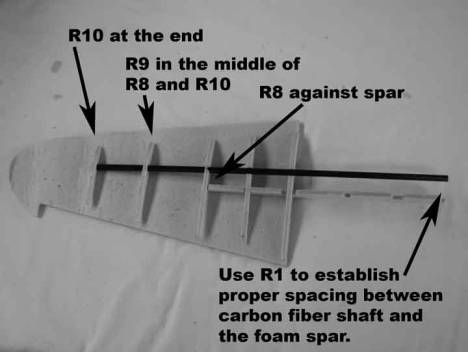
Orient R10 at the end of the spar shaft as shown. Orient rib R8 against the foam spar as shown. Position R9 between R10 and R8, make sure the ribs are all parallel.
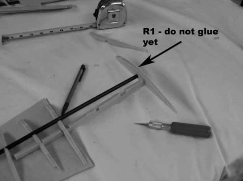
Place rib R1 at the inboard side of the spar carbon fiber shaft and snap it into the foam wing spar. Do not glue at this time. This rib is used to properly space the foam spar and the carbon fiber shaft. Review the assembly for proper position and alignment. When completely satisfied glue the entire assembly with the exception of R1. R1 is for alignment purposes only. The best way to glue the assembly is to place Gorilla glue on the bottom of the ribs and foam spar, spray the bottom wing tip panel with water, then use straight pins to secure everything.
Repeat the above process to build up the other wing tip. Build the two side by side to insure you do not build two right wing tips, build one right and one left.
Set aside and let the glue fully cure.
Wing Root Assembly
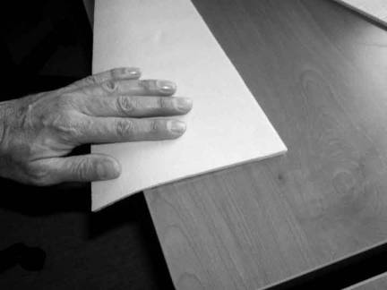
Grab the wing root bottom panel. The bottom panel has the two horizontal slots for the foam wing spar. Gently roll the leading edge over a table edge to put a small upward curl into the leading edge.
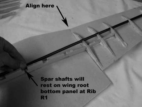
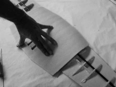
Snap the foam wing spar into the slot in the wing root bottom panel and align the outer wing panel against the root panel as shown in the photo. Slide ribs R1,R2,R3,R4 and R5 onto the wing spar shaft and snap the ribs into the foam spar.
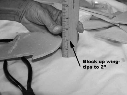
Block up the wing tips 2 inches for the proper diheadral.
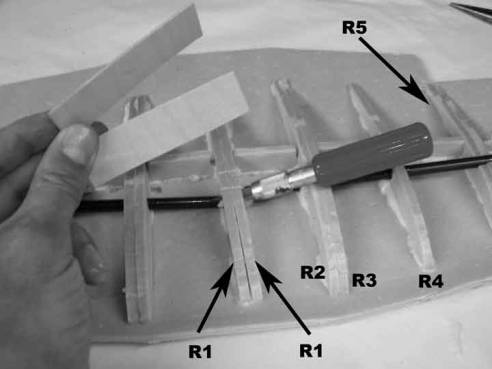
Position ribs R1-R4 as shown. When all of the ribs are aligned properly, glue the assembly together. Use straight pins to secure the foam ribs to the wing panel. Make sure the outer wing panels are securely butted and aligned to the wing root panel.
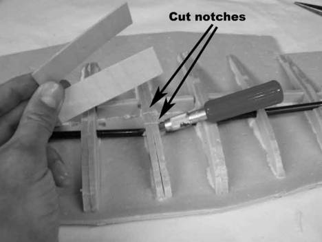
Once the glue has cured locate the two plywood wing braces. Cut two notches through the two R1 ribs and test fit the two ply braces. These will be used to join the two carbon fiber shafts.
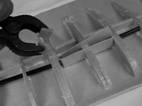
Use a generous amount of Epoxy to sandwich the carbon fiber spars between the wing braces. The wing braces should not protrude above the top of R1 and R2. Use a clamp to secure the braces while the epoxy cures.
Aileron Control Linkage
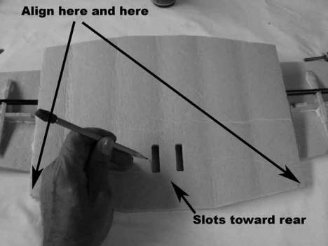
Lay the Wing root top panel into position and mark the location of the two slots onto the lower wing panel with a pencil. This will help locate the aileron control linkage.
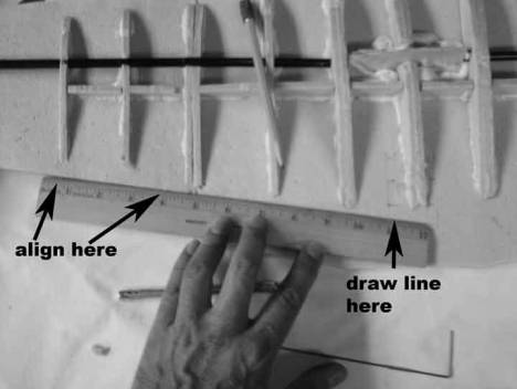
A ruler is used to show the proper position of the aileron linkage. Align the ruler with the wing’s trailing edge where the aileron will hinge. Draw a line projecting this edge onto the wing root panel bottom as shown.
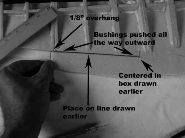
Using the pencil lines, position the aileron linkage as shown. The linkage should be placed slightly rearward of the line defining the aileron hinge point. The inboard bend of the linkage should point up and should be centered in the box drawn to represent the location of the slots in the top panel. The outboard bend of the linkage should point rearward and should overhang the wing root panel by about an 1/8” or so. The linkage bushings should be pushed all the way to the ends of the linkage so there will be not side to side play.
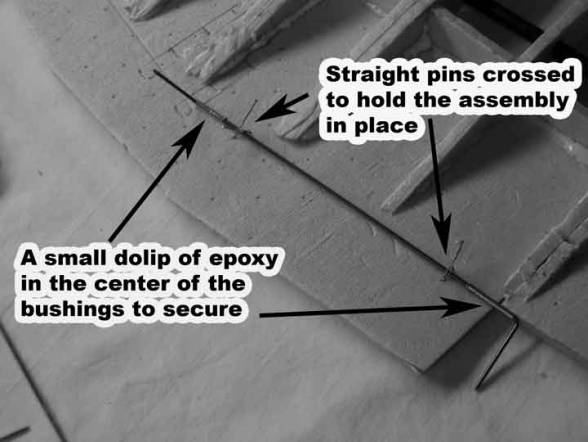
Secure the aileron linkage in place with several straight pins. Use a small dollop of epoxy to secure the bushings to the foam root panel. Be careful not to get epoxy on the music wire as this will hinder its ability to move freely. Once the epoxy cures, insure the aileron linkage is aligned properly and the linkage moves freely.
Skinning the Wing
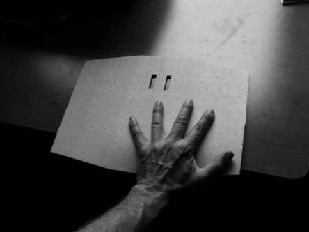
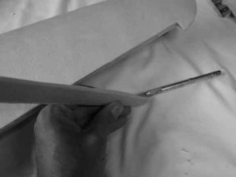
Gently roll the leading edge of the wing root top panel over a table edge to get a bit of curvature. The slots are toward the trailing edge.
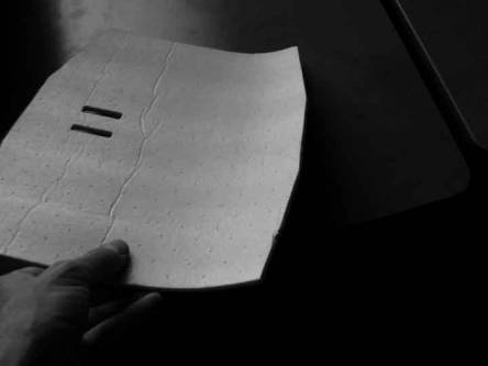
Carefully work the leading edge into the shape as shown.
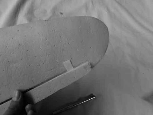
Trim the corner off the inside of the leading edge. A triangular shaped piece will be removed.
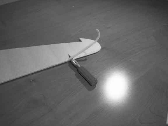
Position the wing root tip panel as shown. Align the part with the rear of the wing. If needed, trim the leading edge to match the bottom panel. Once you are satisfied with the fit, glue into place. Straight pins should be used to hold the skin down against the ribs. Packing tape works well to hold the leading and trainling edges together shile the glue cures. Be careful not to get glue on the aileron linkage, and after the glue has cured, insure that the linkage still moves freely.
Prepare the outer wing top panels as you did with the center wing panel. Roll the leading edge over a table to get a gentle curl on the leading edge.
Trim the corner off the inside of the leading edge. The wing tip can also be thinned for a nicer finished look.
Align the outer wing panel. Use the aileron slot to align the outer top wing panel. When satisfied of the fit apply gorilla glue to the top of the ribs, the spar and the leading and trailing edges of the bottom wing panel. Wet the inside of the outer wing panel top sheet and secure. Packing tape works very well as it closes all of the gaps and gives very even holding power. If there is any bulging, straight pins can be used to secure the top skin to the ribs.
Installing the Ailerons
Trim both corners off the front edge of the ailerons. This will result in a nice triangular shape for the hinged action of the aileron.
Each aileron is secured with three hinges. Cut a slot 1” from each end of the aileron and in the center of the aileron. Be carelful to cut the slot straight (also be careful not to cut yourself during this operation).
Install the hinge in the aileron. Use a small amount of glue. If the glue squeezes out into the area between the aileron and the wing’s trailing edge, the hinge action will be impacted. Lay the aileron against the wing trailing edge as shown and mark the location of the hinges. Cut slots in the wing’s training edge.
Press the aileron against the aileron control horn, then carefully press the wire into the aileron. Insure it goes in straight, it may take several tries. Satisfy yourself with the aileron positioning—insure it does not hit the wing root or the wing tip, you may need to trim the length of the aileron. Finally glue the control wire and hinges to secure the aileron. Use plenty of glue to secure the aileron control wire, but do not gum up the wire where it enters the bushing. Be sparing of the glue used to secure the hinges so as to not restrict their movement.
Congratulations! This concludes the construction of the wing. Now it is time to finish and paint your model.